
Current makes heat wherever it flows — that is normal and unavoidable. A hotspot is heat where the design did not intend it, or more of it than the design intended. And because heat is produced by current meeting resistance, asking "what causes a hotspot?" is really asking "where did unexpected resistance — or unexpected current — come from?" There are three common answers, and they leave different fingerprints.
Signature one: heat at a point — the connection.
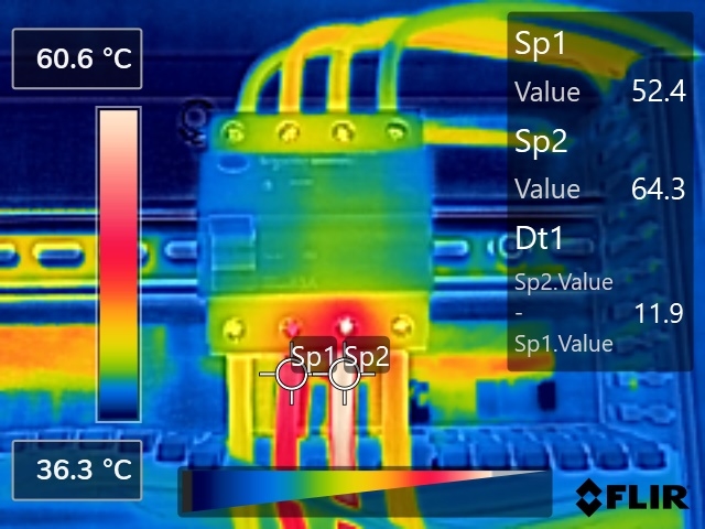
A loose, corroded or poorly-made termination adds resistance at a single point, and the current turns that resistance into heat exactly there. The signature is unmistakable: the hottest pixel sits at the joint itself, and the temperature falls away visibly along the conductor. In the image above, one phase's termination runs nearly twelve degrees above its sibling on the same breaker, under the same load — the comparison that turns a warm picture into a finding.
This is the cause that deserves the most respect, for two reasons. It is self-accelerating — heat oxidises the contact, oxide adds resistance, resistance adds heat — and it is silent: no tripping, no flicker, nothing to notice from outside until the joint chars or fails. The fix is mechanical and local: isolate, inspect, clean or re-make the termination, replace what the heat has already damaged — and then re-scan under load to confirm the fault is actually gone, because heat-damaged conductor can keep the resistance even after a perfect retorque.
Signature two: heat along the whole path — overload.
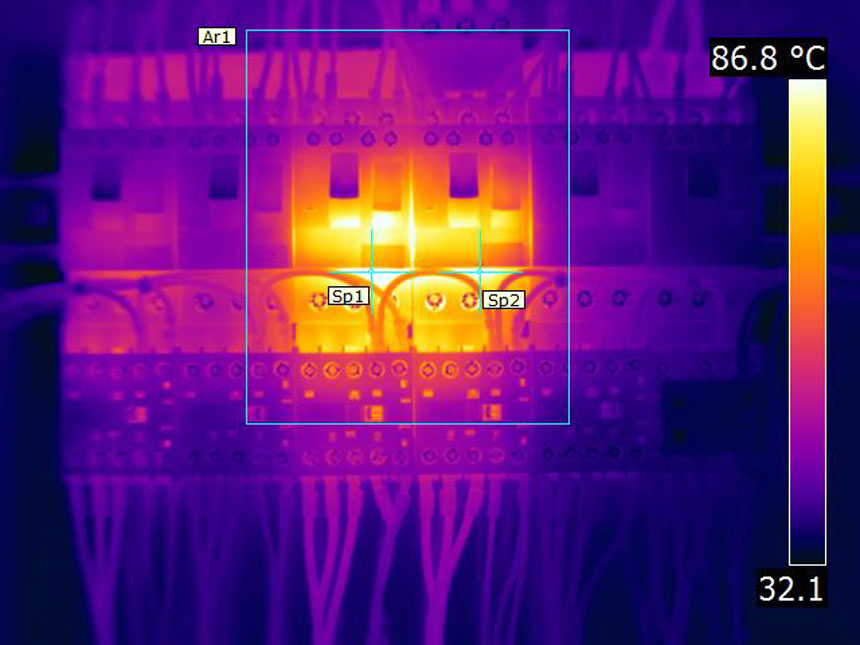
When a circuit carries more current than it was designed for, there is no single point of failure to glow — everything in the path warms together: the cable along its length, the breaker body, the contactor. In the image above, two contactors read more than fifty degrees over the board around them, whole-body, evenly. Nothing is loose; the circuit is simply doing more work than it should.
The fix is electrical arithmetic, not a spanner: measure the actual load, then redistribute it, shed it, or upsize the circuit to carry it. This is where misdiagnosis gets expensive — a technician who reads "hotspot" and retorques every termination on an overloaded circuit has fixed nothing, and the next thermal image will show the same glow. The shape of the heat was saying so all along.
Signature three: one warm phase, everywhere — imbalance.
Three-phase systems want their load shared roughly equally. When too much of it sits on one phase, that phase's conductor, terminals and breaker pole all run warmer than their siblings — not at one point, but at point after point across the board. The signature is comparative: scan the three phases anywhere on the system and the same one keeps winning.
We found exactly this at a Shah Alam manufacturing plant — a distribution board carrying a Danger-rated unbalanced load, and, on the same board, a loose connection: two different causes, two different signatures, one panel. The imbalance fix is planning work — move loads between phases until the sharing is sane — and it often hides behind years of small additions, each one placed on "whichever phase was convenient."
Two more shapes worth knowing.
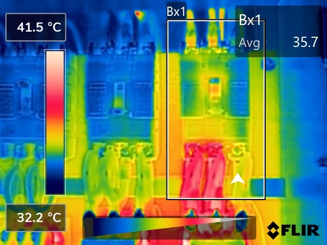
The failing device. Sometimes the terminations are sound and the load is sane, but one breaker still runs hotter than its identical neighbours — the resistance is inside: worn contacts, a weakening mechanism. The device is the component; the fix is replacement, on evidence, before it fails closed or welds shut.
A failing device does not always present hot, which is what makes the image above worth reading twice. Where one pole runs cold while its siblings carry load, that pole has stopped conducting — the same conclusion reached from the opposite direction. Check the obvious causes first: the load on that phase may simply be off. But on a balanced three-phase circuit that should be drawing current on all three, a cold pole on an otherwise loaded breaker points at the device itself.
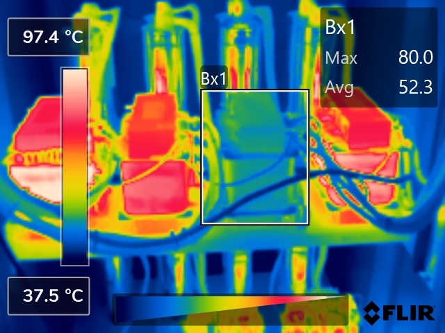
The cold anomaly. The camera's least famous finding: a unit that should be warm and is not. A cold element in a working bank, a cold pole on a loaded breaker, a cold conductor on a live circuit — something has failed open, a fuse has gone, a phase has dropped. Nothing will burn, but something has already stopped working, and nobody has noticed yet.
What to do with a warm something.
Do not open the panel to look — a developing fault is exactly the wrong thing to expose, and the eye cannot see resistance anyway. Get the panel scanned under real operating load, because every signature above depends on current flowing: a proper survey reads the shape, compares like with like, and rates the severity on a printed scale — monitor, planned repair, or act now. Then match the fix to the cause, not to the word "hotspot": re-make the joint, re-plan the load, rebalance the phases, or replace the device — and close the finding with an after-image, not an invoice.
Retrieved from https://amkatechnologies.com/insights/electrical-panel-hotspot-causes
Published 30 July 2026. AMKA Technologies Sdn Bhd, SSM 202301041763 (1535682-T).