
The part of the installation nobody walks past.
On 12 August 2026, a fire broke out on the roof of a factory in Meru, Klang. According to the account and site photographs published by Balai Bomba dan Penyelamat Kapar, it involved a solar array of roughly 300 by 50 feet, about one per cent of the area burned, factory workers brought it under control with CO2 extinguishers, and the brigade arrived nine minutes after the call. No cause has been made public, and nothing below should be read as a claim about what happened there.
What the incident does illustrate is a structural problem with rooftop generation. A distribution board inside a plant room gets walked past daily. An array on a roof is visited when something is already wrong with the yield figures. Its DC circuits carry current through every daylight hour, its connectors sit in sun and rain for a decade, and the first evidence of a deteriorating joint is heat that nobody is positioned to see.
What heat means on an array.
Infrared thermography reads surface temperature, and on a PV installation the surface tells several different stories depending on the shape of the pattern.
A single hot cell
One cell markedly hotter than the rest of its module. A cell that is shaded, cracked or mismatched can be driven into reverse bias by the string around it and dissipate power instead of producing it.
A hot substring
A block of cells warm together in a patchwork pattern. That geometry usually points at a bypass diode conducting when it should not, or at a broken interconnection within the module.
A uniformly warm module
The whole module elevated against its identical neighbours, which points to a series resistance or a connection problem carrying the module's full current rather than to a cell defect.
A hot junction box or connector
Heat concentrated at a termination rather than on the glass. This is the pattern that matters most for fire risk, because it is resistance in a current path inside a plastic enclosure.
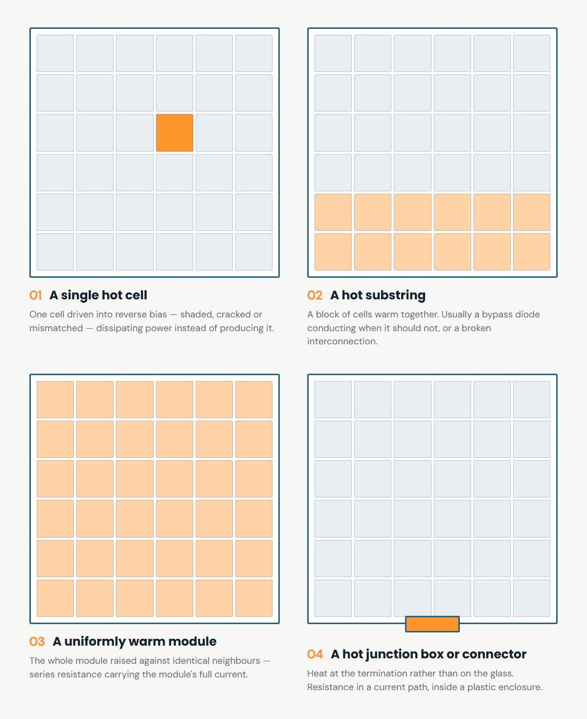
These are indications, not diagnoses. The same warm patch can be produced by soiling, by a reflection of the sun off glass, or by a module at a slightly different tilt. What makes a pattern into a finding is that it deviates from a fair reference under a known condition, and that the deviation survives a second look.
Why a fault on one module is not confined to it.
A hot cell or a failing connector is a problem for its own module. What makes it a problem for the installation is that the neighbours are not separated from it in any meaningful way. Modules share racking, string cabling runs continuously from one to the next, and the whole array sits over a cavity between panel and roof. A module that ignites is surrounded by combustible material with an unbroken path to it.
The materials matter more than they look. Backsheets are commonly PET or PVF laminates with flame-retardant properties, but the EVA encapsulant between glass and cells is flammable and gives off hydrocarbon gases as it degrades thermally. And on the DC side there is no current zero crossing to quench an arc the way there is on AC, which is why a PV arc tends to sustain once it establishes rather than self-extinguishing.
The geometry turns out to govern how fast this travels, and not gently.
In experiments on horizontal flame spread underneath PV modules, reducing the gap between module
and roof from 20 cm to 17 cm raised the flame spread rate from 0.37 mm/s
to 2.41 mm/s — a step change at a critical gap height rather than a gradual
trend, with accelerations reported up to 38 times baseline from a 2–3 cm difference.
Fire Safety Journal, vol. 120, art. 103027 (2021)
Read that with its limits attached. The experiments used PMMA samples as a proxy for the combustible underside, not complete modules, so the numbers describe the roof-cavity mechanism rather than predicting any particular array. What they establish is the shape of the thing: spread under an array is governed by mounting geometry, and a small difference in clearance can separate a slow fire from a fast one.
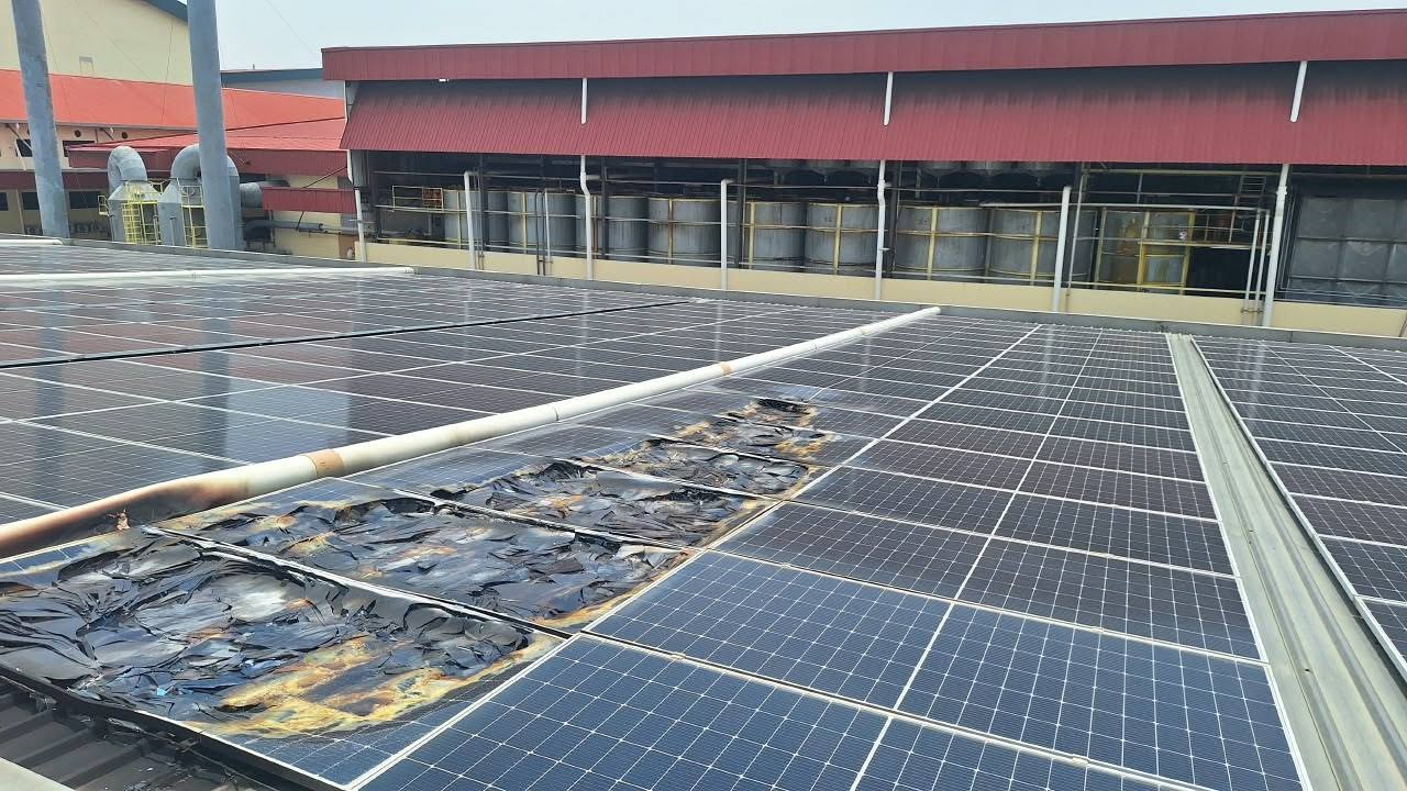
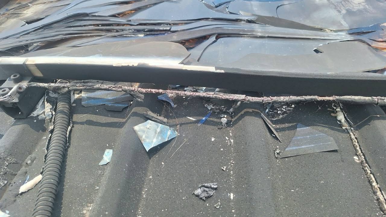
Meru is the containment case, and it is worth saying so rather than letting the numbers above imply otherwise. About one per cent of that array burned, workers reached it with CO2 extinguishers, and the brigade arrived in nine minutes — an outcome that turned on how fast people got to the roof, not on anything a camera had seen beforehand. Spread is a risk, not a certainty, and the geometry that governs it is set at installation rather than found on a scan.
So the honest claim is narrow. A thermal pass does not stop a fire, and nothing here says it would have changed that afternoon. What it does is find the resistive joint while it is still a joint — and the reason that matters more on a roof than in a plant room is that the consequence is not bounded by the module it starts in.
The conditions that make the reading valid.
A PV module heats because of the current it is producing. That single fact governs when a scan is worth taking. Under a thin overcast, an array is barely working, faults barely warm, and an image taken in those conditions can look reassuringly uniform while proving almost nothing.
IEC 62446-3, the standard covering outdoor infrared thermography of photovoltaic modules and plants, sets a minimum irradiance for a valid inspection along with conditions on wind and on the angle the camera looks from.
Viewing angle matters for a reason peculiar to this asset: module glass is reflective in the infrared as well as the visible. Look at a panel square-on and the camera can read the sky, or itself, rather than the module. Scans are taken off-normal for that reason, and a report that does not record irradiance, ambient temperature, wind and the angle its images were taken at has left out the information a reader needs to judge it.
Flown, or on foot.
A drone reads the array face quickly and at consistent geometry, which is what makes comparison across hundreds of identical modules possible at all. It is also the safe way to cover a roof that would otherwise need people walking between rows. What it does not read is the electrical side: the inverters, DC isolators, combiner boxes and distribution panels where connection heating appears and where the interface with the rest of the installation sits.
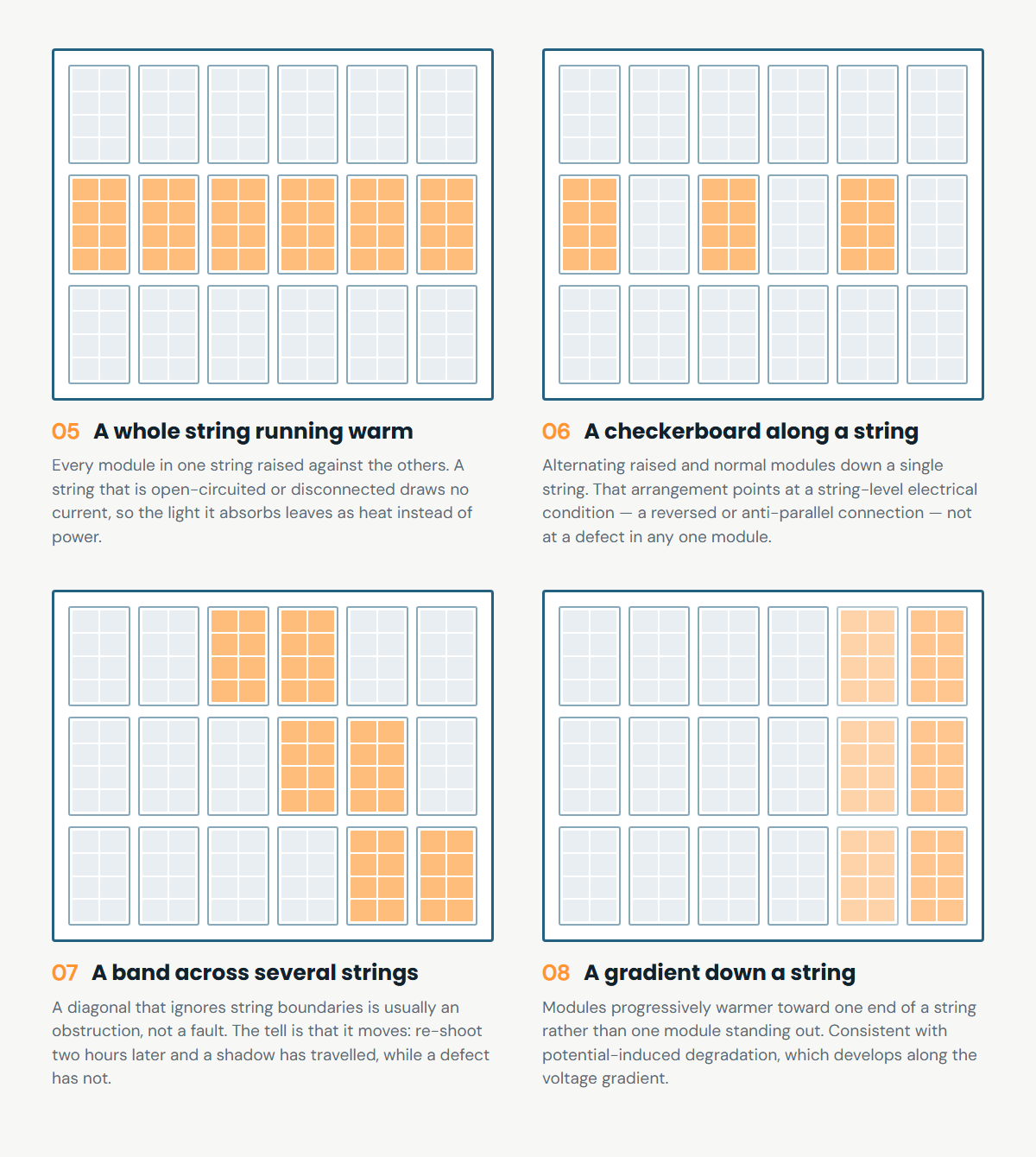
Coverage at that scale is not only a matter of speed. A second family of patterns exists that no single module can show you, because the evidence is the arrangement across modules — which string, in what order, ignoring which boundaries.
AMKA scans the electrical side on foot as part of a building thermographic inspection, and the array itself is covered by a specialist drone operator who owns the aircraft, the flight planning and the operational approvals. The thermal interpretation and the written findings come back to us either way, so the roof and the switchboard end up in one report with one rating logic rather than two documents that do not speak to each other.
What the scan cannot answer.
Thermography sees surfaces, and only what is hot at the moment of the scan. It does not see inside a sealed junction box, only the heat that reaches the outside of it. It does not measure insulation condition, which is what insulation resistance testing and IV curve tracing are for. It does not predict when a warm connection will fail, only that it is warmer than it should be today. And a clean scan taken on a dull afternoon says considerably less than an ordinary one taken at full generation.
Reading an image also authorises nothing. Opening, isolating and working on any part of an energised installation stays with site electrical rules and the responsible competent person.
Where this belongs in a maintenance routine.
Malaysia's Electricity Regulations 1994 are specific about how often a competent person must attend, that a written report must follow, and that a record book stays open to the Commission. They do not define what the inspection must look for, and nothing in them requires an installation to be examined while it is carrying its normal working load.
That gap is ours to close voluntarily or not at all. A periodic routine that inspects the plant room thoroughly and never looks at the roof under generation is not a complete routine; it is a complete routine minus the one part of the installation that runs unattended in the weather. Our own view is that a thermal pass under load belongs in the schedule for any site with a rooftop array, at a frequency the site's own risk justifies.
Retrieved from https://amkatechnologies.com/insights/rooftop-solar-thermal-inspection
Published 19 August 2026. AMKA Technologies Sdn Bhd, SSM 202301041763 (1535682-T).